Selling fast!
Get yours while you can.
SU-DPATCH
Couldn't load pickup availability
Prices valid in USA, Canada, and PR only.
| Order code | Description | Details |
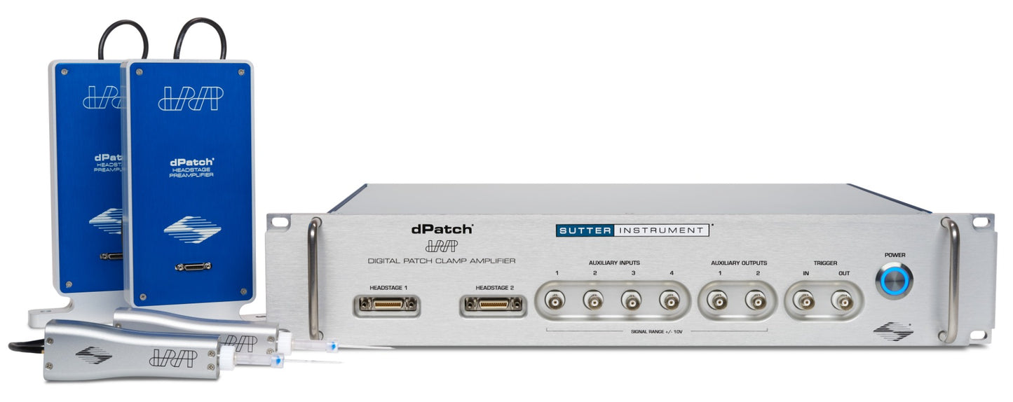
| SU-DPATCH | dPatch system with one headstage and preamp | Includes: dPatch system with one headstage and preamplifier, 505671 pipette holder, model cell, screw terminal for digital outputs, rack mounting hardware; SutterPatch® software suite with Igor Pro license |
| SU-DPATCH-2 | dPatch system with two headstages and preamp | Includes: dPatch system with two headstages and preamplifiers, two 505671 pipette holders, two model cells, screw terminals for digital outputs, rack mounting hardware; SutterPatch® software suite with Igor Pro license |
Sutter has a long history of standing by our products and continually improving them. While other amplifiers on the market haven't been updated in 20 years, the dPatch will continue to be developed and supported WELL into the future. All of our products are built in the USA, and we offer free support should you need any help.
One unique feature with dPatch is the headstage data sampling system. Each headstage is continually sampled at 5 MHz. Output filtering has thirteen settings between 100 Hz and 1 MHz. A resolution of 18 bits is achieved at 1 MHz. For lower filter settings, automatic downsampling increases resolution while optimizing data rates. At a bandwidth setting of 1 kHz, the dPatch system provides a signal resolution of better than 22 bits.
Active cooling causes numerous problems that actually create more "noise" in the long run. Active cooling in amplifier headstages use Peltier cells, which cool the electronics for slightly better performance, but generate considerable heat on the opposite side of the cell. The heat generated causes thermal drift which makes it almost impossible to stay patched while doing single-channel work. This is THE MOST COMMON source of what users perceive as "manipulator drift". As a company that makes micromanipulators, we are highly sensitive to the performance of the system within a complete electrophysiology rig.
Active cooling can help get a slightly better noise specification on paper, but in the real world the disadvantages far outweigh the slight gain in specsmanship. One of the development goals of the dPatch headstage was achieving a comparable noise performance at room temperature, without the need for a cooled headstage. In the two resistive feedback modes, the dPatch amplifier is even quieter than any of the competitor systems. In addition, the limited life expectancy of Peltier elements causes reliability concerns that we found unacceptable.
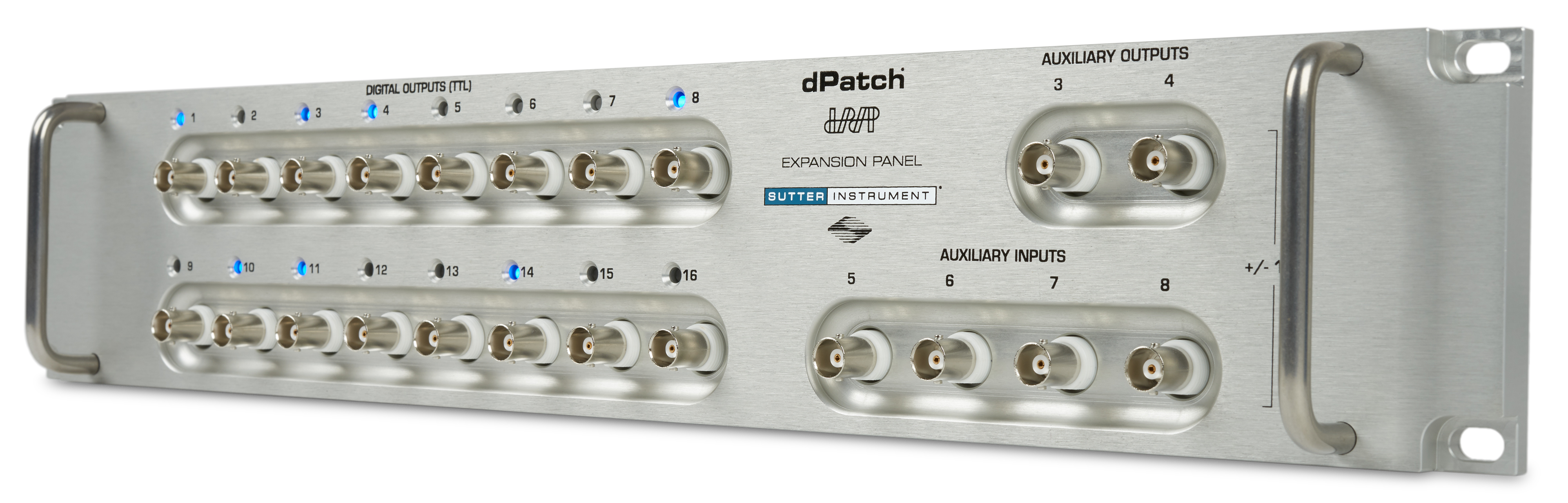
Using a multiplexer-free design, the dPatch provides 8 fully differential analog input channels, 4 analog output channels, and 16 digital outputs (TTL). All I/O channels are sampled continuously (200 kHz for analog inputs, 250 kHz for analog and digital outputs) and available through the user interface.
The dPatch amplifier system, in combination with SutterPatch software, has been engineered to automatically capture and store all amplifier settings, stimulus information and external experiment parameters, and associate them in time with the raw data traces. This includes all amplifier and acquisition settings, as well as timing and progress of the experiment. Fully integrated computer control of the amplifier stages means that the acquisition software is aware of the internal state of the amplifier and digitizer at all times and can track any changes that may occur. This is independent of whether a change is triggered automatically or initiated by the user.
The patented digital architecture of the dPatch amplifier system provides an ideal platform for dynamic clamp. The dPatch is powered by a system-on-chip which provides parallel processing across a Field Programmable Gate Array (FPGA) and two high-speed ARM core processors. Several sophisticated dynamic clamp models are implemented within this architecture. In each model, the update of the applied current values occurs without communication between the dPatch and a computer. Depending upon the complexity of the model, update rates of up to 500 kHz can be achieved.
In addition to status changes in connected hardware that are automatically tracked, the researcher can manually trigger tags to document events like stimulus application using instruments not connected to the amplifier. Information about environmental parameters and a more detailed specification of sample properties can be recorded and stored with the raw data. A total of over 650 metadata attributes are supported. Examples include: animal species, genotype, date/time when a cell sample was prepared, recording solutions, pipette resistance, hardware properties, and detailed information about stimuli applied.
SutterPatch software has been designed to simplify the navigation and analysis of complex datasets. The scope window supports multiple view modes in both two-dimensional and an innovative three-dimensional display. The 3D view is particularly useful during assay development. Built on top of the latest version of the proven Igor Pro platform, SutterPatch combines native Igor Pro functionality with a wealth of features that are tailored to electrophysiology applications. Both the newcomer and the experienced user of patch clamp programs will feel comfortable using SutterPatch software.
Application modules provide focused functionality for particular applications.
Currently available:
While the dPatch System is ready for cutting-edge research, its feature set makes it immediately valuable in any lab setting.
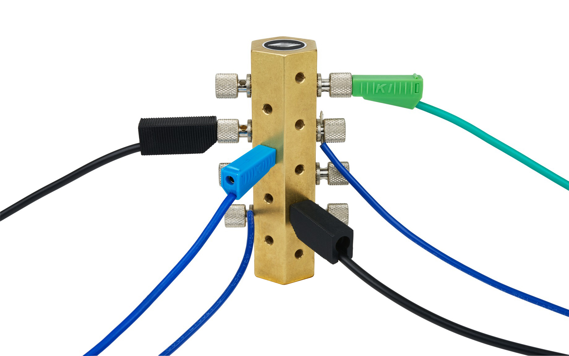
Ground Point
The Ground Point (#505673) provides reliable, low resistance connections for a star ground configuration, the proven method to avoid ground loops in any electrophysiology setup. Accepts 9 banana plugs + 8 bare wires up to 10 gauge or banana plugs. The baseplate mounts directly on imperial or metric air table tops with the included ¼-20 and M6 screws. Made of solid, machined brass with plated banana/clamp connectors.
dPatch Expansion Panel
The dPatch Integrated Digital Patch Clamp Amplifier is a computer-controlled single- or dual-headstage system optimized for both single-channel and whole-cell recording applications.
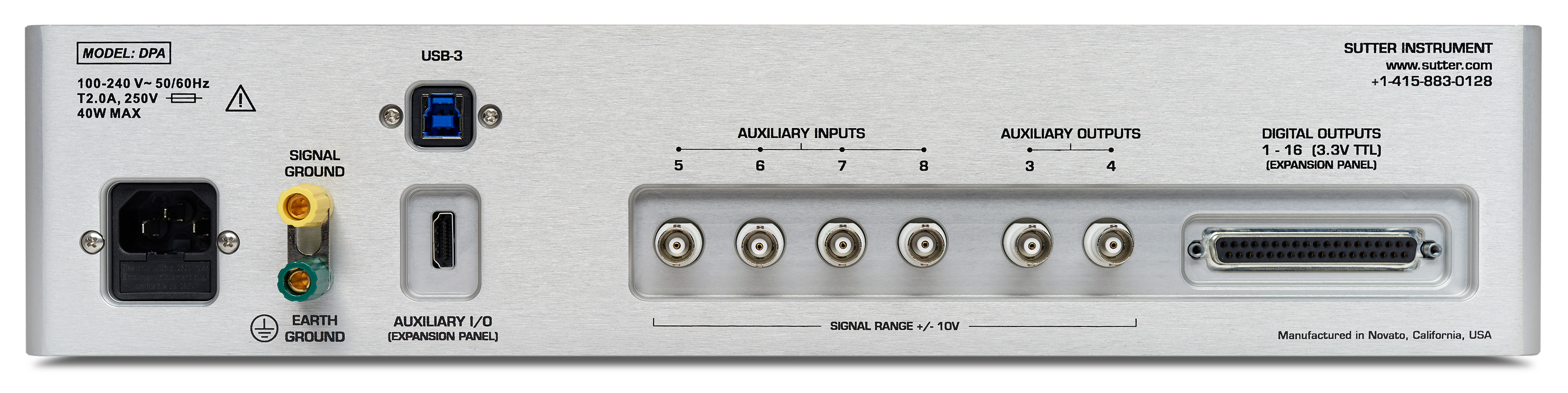
back panel of dPatch. (Click for larger view)
Element |
Bandwidth |
10 kHz BW |
Compensation Range |
Resistance Range |
Capacitance Range |
|
|---|---|---|---|---|---|---|
* Capacitive feedback range is optimized for single-channel voltage clamp recordings. Whole-cell compensation and current clamp mode are disabled with this range.
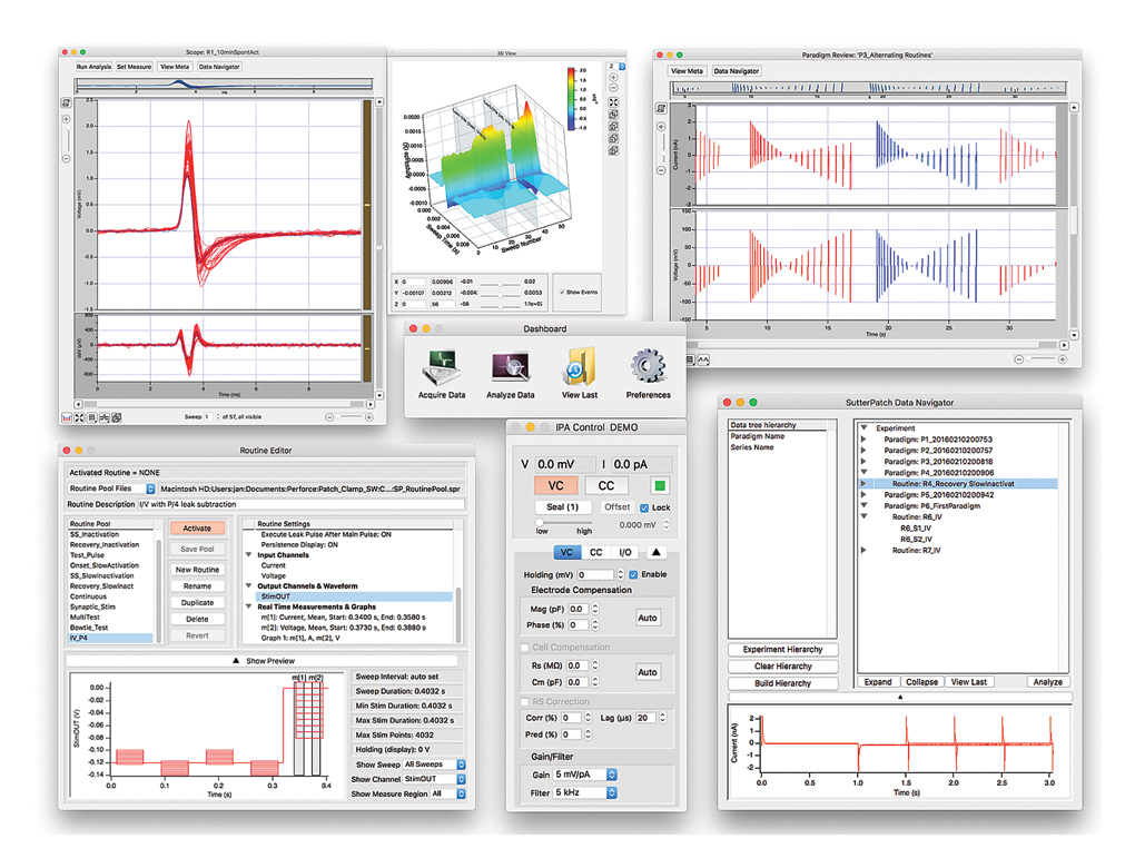
Screenshot of SutterPatch Software
TECHNICAL SPECIFICATIONS
Dimensions
dPatch: 19 in x 11 in x 3.5 in | 48.2 cm x 28 cm x 9 cm
dPatch Preamplifier: 7.6 in x 3.5 in x 1.2 in | 19.5 cm x 9 cm x 3 cm
dPatch Headstage: 3.7 in x 1.1 in x 0.66 in | 9.5 cm x 2.9 cm x 1.7 cm
Weight
dPatch: 15 lbs | 6.8 kg
Electrical
110/240 Volts
50/60 Hertz power line
*Patent No. US 10,393,727 B2
RoHS Compliant
DPATCH CE Certificate![]()


SYSTEM REQUIREMENTS
Minimum Configuration:
Recommended Configuration for Bandwidths of >50 kHz:
SUTTERPATCH® Data Acquisition Management System and Analysis Software: Included with all Sutter Instrument Amplifier Systems
1 Operating systems installed within virtualization software platforms such as VMware and Parallels are not supported.
2 At this point, WaveMetrics does not fully support Igor Pro on Mac computers based on the Apple Silicon M1 architecture. See https://www.wavemetrics.com/news/igor-and-apple-arm-processors for technical details. Preliminary experiments indicate that SutterPatch Software runs on these computers, both under Igor Pro 8 and 9, and with each of the Sutter Amplifier Systems connected. However, as with each new technology, we cannot fully exclude incompatibilities.
3 USB 3.0 ports are compatible with USB 2.0 High Speed specifications.
Slower USB 2.0 ‘full-speed’ ports, which are sometimes found on older Windows PCs or USB add-in cards, are not supported.
To check for High Speed USB 2.0 or USB 3.0 on a PC computer running Windows, look in the Control Panel > Device Manager > Universal Serial Bus controllers section for “Enhanced” host controllers. As this does not provide any mapping information to the computer’s physical ports, and there can be a mix of USB port versions, you should check individual USB ports for USB 2.0/3.0 High Speed operational performance. As a visual indicator, USB 3.0 ports are often color coded blue.
USB hubs are not supported. USB add-in cards, even if they formally meet High Speed or Super Speed specifications, are not recommended. They are often architecturally configured as USB hubs and may lead to intermittent transfer errors that are hard to troubleshoot.
![]()