Selling fast!
Get yours while you can.
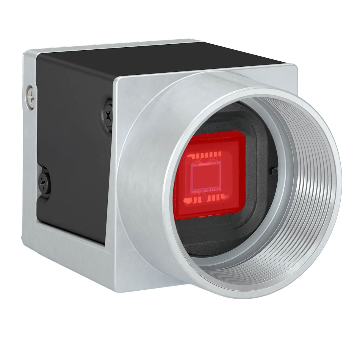
USBCAM1-2
Couldn't load pickup availability
Prices valid in USA, Canada, and PR only.
| Features | USBCAM1-2 | USBCAM1-1-8 | USBCAM1-3 |
| Resolution | 1280 px x 1024 px (1.3MP) | 3088 px x 2064 px (6.4MP) |
1456 x 1088 (full resolution) / 1440 x 1080 (default resolution) – 1.6MP *You can change the resolution by changing the image ROI. |
| Sensor Type |
onsemi PYTHON NOIP1SE1300A Progressive scan CMOSGlobal Shutte
|
Sony IMX178LQJ-C Progressive scan CMOS Rolling shutter |
Sony IMX273LQR-C Progressive scan CMOS Global shutter |
| Sensor Format | 1/2” | 1/1.8” | 1/3” |
| Effective Sensor Diagonal | 7.9mm | 8.92mm | 6.3mm |
| Pixel Size (H x V) | 4.8 x 4.8 µm | 2.4 x 2.4 µm | 3.45 x 3.45 μm |
| Frame Rate |
203 fps (at fast sensor readout mode) 169 fps (at normal sensor readout mode) |
59.6 fps (Device Link Throughput Limit Mode set to Off) 56.4 fps (default settings) |
227 fps |
| Mono / Color | Color | ||
| Pixel Format | *See Pixel Formats Data Sheet Under Resources | ||
| Image Data Interface | USB 3.0, nominal max. 5 Gbit/s (SuperSpeed) | ||
| Synchronization | Via hardware trigger Via software trigger Via free run |
||
| Exposure Time Control | Via hardware trigger Programmable via the camera API |
||
| Camera Power Requirements | ≈3.0 W (typical) @ 5 VDC ≈3.3 W (max.) |
||
| I/O Lines | 1 opto-coupled input line 1 opto-coupled output line 2 general purpose I/O (GPIO) lines |
||
| Lens Mount | C-mount | ||
| Size (L x W x H) | 29.3 x 29 x 29 mm (without lens mount or connectors) 48.2 x 29 x 29 mm (with lens mount and connectors) |
||
| Weight | 80g | ||
| Conformity | CE (includes RoHS), EAC, UKCA, UL Listed, FCC, GenICam 2.x (including PFNC 2.x and SFNC 2.x), IP30, USB3 Vision, REACH, KC *See conformity documentation in user manual |
||
| Software |
Basler pylon Software Suite (version 4.0 or higher) Available for Windows, Linux x86, Linux ARM, macOS, and Android |
||

*The spectral response curve excludes lens characteristics, light source characteristics, and IR cut filter characteristics.

*The spectral response curve excludes lens characteristics, light source characteristics, and IR cut filter characteristics.

*The spectral response curve excludes lens characteristics, light source characteristics, and IR cut filter characteristics.
Color cameras are equipped with an IR cut filter. The filter is mounted in a filter holder inside the lens mount.
The IR cut filter has the following spectral characteristics:
| Wavelength [nm] | Transmittance |
| 450–610 | Tmin > 90 % |
| 450–620 | Tavg > 93 % |
| 645 ± 10 | T = 50 % |
| 700–1070 | Tmax < 4 % |
| 690–1070 | Tavg < 1 % |
Camera Dimensions and Mounting Points:

Environmental Requirements: Temperature and Humidity
| Housing temperature during operation | 0–50 °C (32–122 °F) |
| Humidity during operation | 20–80 %, relative, non-condensing |
| Storage temperature | -20–80 °C (-4–176 °F) |
| Storage humidity | 20–80 %, relative, non-condensing |
| Housing temperature according to UL 60950-1 | max. 70 °C (158 °F) |
| Ambient temperature according to UL 60950-1 | max. 30 °C (86 °F) |
You must supply camera power that complies with the Universal Serial Bus 3.0 specification. The camera's nominal operating voltage is 5 VDC, effective on the camera's connector.
| Voltage | Description |
| 30 VDC | Absolute maximum. This voltage must never be exceeded. Doing so may damage the camera and voids the warranty. |
| 0–24 VDC | Safe operating range. |
| 0–1.4 VDC | Indicates a logical 0 (with inverter disabled). |
| >1.4–2.2 VDC | Region where the logic level transition occurs; the logical state is not defined in this region. |
| >2.2 VDC | Indicates a logical 1 (with inverter disabled). |
| Voltage | Description |
| 30 VDC | Absolute maximum. This voltage must never be exceeded. Doing so may damage the camera and voids the warranty. |
| 3.3–24 VDC | Safe operating range. |
| <3.3 VDC | Unreliable I/O output. |
| Voltage | Description |
| 30 VDC | Absolute maximum. This voltage must never be exceeded. Doing so may damage the camera and voids the warranty. |
| 0–24 VDC | Safe operating range. The minimum external pull-up voltage is 3.3 VDC. |
| 0–0.8 VDC | Indicates a logical 0 (with inverter disabled). |
| >0.8–2.0 VDC | Region where the logic level transition occurs; the logical state is not defined in this region. |
| >2.0 VDC | Indicates a logical 1 (with inverter disabled). |
| Voltage | Description |
| 30 VDC | Absolute maximum. This voltage must never be exceeded. Doing so may damage the camera and voids the warranty. |
| 3.3–24 VDC | Safe operating range. |
| <3.3 VDC | Unreliable I/O output. |
USB 3.0 Cable
*It is recommended to use the USB 3.0 cable included with the camera
Physical Interface

Connector Pinout

| Pin | Line | Function |
| 1 | Line 3 | General purpose I/O (GPIO) line |
| 2 | Line 1 | Opto-coupled I/O input line |
| 3 | Line 4 | General purpose I/O (GPIO) line |
| 4 | Line 2 | Opto-coupled I/O output line |
| 5 | - | Ground for opto-coupled I/O lines |
| 6 | - | Ground for General Purpose I/O (GPIO) lines |